
DIN 2093 Disc Springs
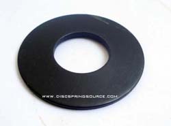
The advantages of disc springs compared to other types of springs include the following:
* A wide range of load/defl ection characteristics
* High load capacity with small deflection
* Space savings – high load to size ratio
* No set under design loads
* Longer fatigue life
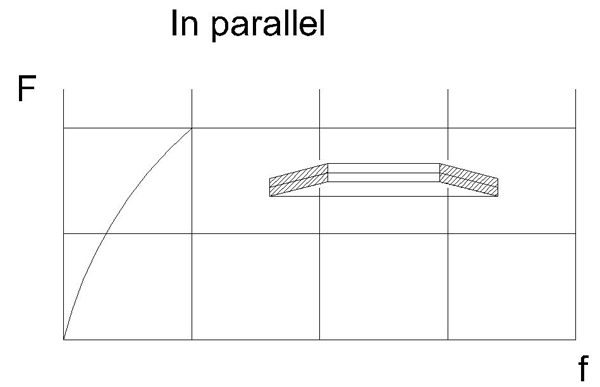
* Inherent dampening especially with parallel stacking
* Flexibility in stack arrangement to meet your application requirements
Disc spring range:
Parts according to Din 2093 disc springs are listed into 3 groups.
Group 1 Material thickness < 1.25mm
Group 2 Material thickness 1.25 - 6.0mm
Group 3 Material thickness > 6.0 - 14mm
Disc spring specification
Standard Disc Springs Unit:inch PDF download
| DIN2093(GB/T1972-2005) | |||||||||||
| Serial A D/t≈18;h0/t≈0.4;E=206000N/mm2 ;μ=0.30 | |||||||||||
| Item no. | D/mm | d/mm | t(t′)/mm | h0/mm | H0/mm | f≈0.75h0 | Q/KG/ 1000pcs |
||||
| f/mm | (H0-f)/mm | F/N | σ om/ |
σⅡ、σⅢ /N/mm2 |
|||||||
| A1 | 8 | 4.2 | 0.4 | 0.2 | 0.6 | 0.15 | 0.45 | 210 | -1200 | 1220* | 0.114 |
| A2 | 10 | 5.2 | 0.5 | 0.25 | 0.75 | 0.19 | 0.56 | 329 | -1210 | 1240* | 0.225 |
| A3 | 12.5 | 6.2 | 0.7 | 0.3 | 1 | 0.23 | 0.77 | 673 | -1280 | 1420* | 0.508 |
| A4 | 14 | 7.2 | 0.8 | 0.3 | 1.1 | 0.23 | 0.87 | 813 | -1190 | 1340* | 0.711 |
| A5 | 16 | 8.2 | 0.9 | 0.35 | 1.25 | 0.26 | 0.99 | 1000 | -1160 | 1290* | 1.05 |
| A6 | 18 | 9.2 | 1 | 0.4 | 1.4 | 0.3 | 1.1 | 1250 | -1170 | 1300* | 1.48 |
| A7 | 20 | 10.2 | 1.1 | 0.45 | 1.55 | 0.34 | 1.21 | 1530 | -1180 | 1300* | 2.01 |
| A8 | 22.5 | 11.2 | 1.25 | 0.5 | 1.75 | 0.38 | 1.37 | 1950 | -1170 | 1320* | 2.94 |
| A9 | 25 | 12.2 | 1.5 | 0.55 | 2.05 | 0.41 | 1.64 | 2910 | -1210 | 1410* | 4.4 |
| A10 | 28 | 14.2 | 1.5 | 0.65 | 2.15 | 0.49 | 1.66 | 2850 | -1180 | 1280* | 5.39 |
| A11 | 31.5 | 16.3 | 1.75 | 0.7 | 2.45 | 0.53 | 1.92 | 3900 | -1190 | 1320* | 7.84 |
| A12 | 35.5 | 18.3 | 2 | 0.8 | 2.8 | 0.6 | 2.2 | 5190 | -1210 | 1330* | 11.4 |
| A13 | 40 | 20.4 | 2.25 | 0.9 | 3.15 | 0.68 | 2.47 | 6540 | -1210 | 1340* | 16.4 |
| A14 | 45 | 22.4 | 2.5 | 1 | 3.5 | 0.75 | 2.75 | 7720 | -1150 | 1300* | 23.5 |
| A15 | 50 | 25.4 | 3 | 1.1 | 4.1 | 0.83 | 3.27 | 12000 | -1250 | 1430* | 34.3 |
| A16 | 56 | 28.5 | 3 | 1.3 | 4.3 | 0.98 | 3.32 | 11400 | -1180 | 1280* | 43 |
| A17 | 63 | 31 | 3.5 | 1.4 | 4.9 | 1.05 | 3.85 | 15000 | -1140 | 1300* | 64.9 |
| A18 | 71 | 36 | 4 | 1.6 | 5.6 | 1.2 | 4.4 | 20500 | -1200 | 1330* | 91.8 |
| A19 | 80 | 41 | 5 | 1.7 | 6.7 | 1.28 | 5.42 | 33700 | -1260 | 1460* | 145 |
| A20 | 90 | 46 | 5 | 2 | 7 | 1.5 | 5.5 | 31400 | -1170 | 1300* | 184.5 |
| A21 | 100 | 51 | 6 | 2.2 | 8.2 | 1.65 | 6.55 | 48000 | -1250 | 1420* | 273.7 |
| A22 | 112 | 57 | 6 | 2.5 | 8.5 | 1.88 | 6.62 | 43800 | -1130 | 1240* | 343.8 |
| A23 | 125 | 64 | 8(7.5) | 2.6 | 10.6 | 1.95 | 8.65 | 85900 | -1280 | 1330* | 533 |
| A24 | 140 | 72 | 8(7.5) | 3.2 | 11.2 | 2.4 | 8.8 | 85300 | -1260 | 1280* | 666.6 |
| A25 | 160 | 82 | 10(9.4) | 3.5 | 13.5 | 2.63 | 10.87 | 139000 | -1320 | 1340* | 1094 |
| A26 | 180 | 92 | 10(9.4) | 4 | 14 | 3 | 11 | 125000 | -1180 | 1200* | 1387 |
| A27 | 200 | 102 | 12(11.25) | 4.2 | 16.2 | 3.15 | 13.05 | 183000 | -1210 | 1230* | 2100 |
| A28 | 225 | 112 | 12(11.25) | 5 | 17 | 3.75 | 13.25 | 171000 | -1120 | 1140 | 2640 |
| A29 | 250 | 127 | 14(13.1) | 5.6 | 19.6 | 1.2 | 15.4 | 249000 | -1200 | 1220 | 3750 |
| Serial B D/t≈28;h0/t≈0.75;E=206000N/mm2 ; μ=0.30 | |||||||||||
| Item no. | D/mm | d/mm | t(t′)/mm | h0/mm | H0/mm | f≈0.75h0 | Q/kg/ 1000pcs |
||||
| f/mm | (H0-f)/mm | F/N | σ om/ N/mm2 |
σⅡ、σⅢ /N/mm2 |
|||||||
| B1 | 8 | 4.2 | 0.3 | 0.25 | 0.55 | 0.19 | 0.36 | 119 | -1140 | 1330 | 0.086 |
| B2 | 10 | 5.2 | 0.4 | 0.3 | 0.7 | 0.23 | 0.47 | 213 | -1170 | 1300 | 0.180 |
| B3 | 12.5 | 6.2 | 0.5 | 0.35 | 0.85 | 0.26 | 0.59 | 291 | -1000 | 1110 | 0.363 |
| B4 | 14 | 7.2 | 0.5 | 0.4 | 0.9 | 0.3 | 0.6 | 279 | -970 | 1100 | 0.444 |
| B5 | 16 | 8.2 | 0.6 | 0.45 | 1.05 | 0.34 | 0.71 | 412 | -1010 | 1120 | 0.698 |
| B6 | 18 | 9.2 | 0.7 | 0.5 | 1.2 | 0.38 | 0.82 | 572 | -1040 | 1130 | 1.03 |
| B7 | 20 | 10.2 | 0.8 | 0.55 | 1.35 | 0.41 | 0.94 | 745 | -1030 | 1110 | 1.46 |
| B8 | 22.5 | 11.2 | 0.8 | 0.65 | 1.45 | 0.49 | 0.96 | 710 | -962 | 1080 | 1.88 |
| B9 | 25 | 12.2 | 0.9 | 0.7 | 1.6 | 0.53 | 1.07 | 868 | -938 | 1030 | 2.64 |
| B10 | 28 | 14.2 | 1 | 0.8 | 1.8 | 0.6 | 1.2 | 1110 | -961 | 1090 | 3.59 |
| B11 | 31.5 | 16.3 | 1.25 | 0.9 | 2.15 | 0.68 | 1.47 | 1920 | -1090 | 1190 | 5.6 |
| B12 | 35.5 | 18.3 | 1.25 | 1 | 2.25 | 0.75 | 1.5 | 1700 | -944 | 1070 | 7.13 |
| B13 | 40 | 20.4 | 1.5 | 1.15 | 2.65 | 0.86 | 1.79 | 2620 | -1020 | 1130 | 10.95 |
| B14 | 45 | 22.4 | 1.75 | 1.3 | 3.05 | 0.98 | 2.07 | 3660 | -1050 | 1150 | 16.4 |
| B15 | 50 | 25.4 | 2 | 1.4 | 3.4 | 1.05 | 2.35 | 4760 | -1060 | 1140 | 22.9 |
| B16 | 56 | 28.5 | 2 | 1.6 | 3.6 | 1.2 | 2.4 | 4440 | -963 | 1090 | 28.7 |
| B17 | 63 | 31 | 2.5 | 1.75 | 4.25 | 1.31 | 2.94 | 7180 | -1020 | 1090 | 46.4 |
| B18 | 71 | 36 | 2.5 | 2 | 4.5 | 1.5 | 3 | 6730 | -934 | 1060 | 57.7 |
| B19 | 80 | 41 | 3 | 2.3 | 5.3 | 1.73 | 3.57 | 10500 | -1030 | 1140 | 87.3 |
| B20 | 90 | 46 | 3.5 | 2.5 | 6 | 1.88 | 4.12 | 14200 | -1030 | 1120 | 129.1 |
| B21 | 100 | 51 | 3.5 | 2.8 | 6.3 | 2.1 | 4.2 | 13100 | -926 | 1050 | 159.7 |
| B22 | 112 | 57 | 4 | 3.2 | 7.2 | 2.4 | 4.8 | 17800 | -963 | 1090 | 229.2 |
| B23 | 125 | 64 | 5 | 3.5 | 8.5 | 2.63 | 5.87 | 30000 | -1060 | 1150 | 355.4 |
| B24 | 140 | 72 | 5 | 4 | 9 | 3 | 6 | 27900 | -970 | 1100 | 444.4 |
| B25 | 160 | 82 | 6 | 4.5 | 10.5 | 3.38 | 7.12 | 41100 | -1000 | 1110 | 698.3 |
| B26 | 180 | 92 | 6 | 5.1 | 11.1 | 3.83 | 7.27 | 37500 | -895 | 1040 | 885.4 |
| B27 | 200 | 102 | 8(7.5) | 5.6 | 13.6 | 4.2 | 9.4 | 76400 | -1060 | 1250 | 1369 |
| B28 | 225 | 112 | 8(7.5) | 6.5 | 14.5 | 4.88 | 9.62 | 70800 | -951 | 1180 | 1761 |
| B29 | 250 | 127 | 10(9.4) | 7 | 17 | 5.25 | 11.75 | 119000 | -1050 | 1240 | 2687 |
| Serial C D/t≈40;h0/t≈1.30;E=206000N/mm2;μ=0.30 | |||||||||||
| Item no. | D/mm | d/mm | t(t′)/mm | h0/mm | H0/mm | f≈0.75h0 | Q/kg/ 1000pcs |
||||
| f/mm | (H0-f)/mm | F/N | σ om/ N/mm2 |
σⅡ、σⅢ /N/mm2 |
|||||||
| C1 | 8 | 4.20 | 0.20 | 0.25 | 0.45 | 0.19 | 0.26 | 39 | -762 | 1040 | 0.057 |
| C2 | 10 | 5.2 | 0.25 | 0.3 | 0.55 | 0.23 | 0.32 | 58 | -734 | 980 | 0.112 |
| C3 | 12.5 | 6.2 | 0.35 | 0.45 | 0.8 | 0.34 | 0.46 | 152 | -944 | 1280 | 0.251 |
| C4 | 14 | 7.2 | 0.35 | 0.45 | 0.8 | 0.34 | 0.46 | 123 | -769 | 1060 | 0.311 |
| C5 | 16 | 8.2 | 0.4 | 0.5 | 0.9 | 0.38 | 0.52 | 155 | -751 | 1020 | 0.466 |
| C6 | 18 | 9.2 | 0.45 | 0.6 | 1.05 | 0.45 | 0.6 | 214 | -789 | 1110 | 0.661 |
| C7 | 20 | 10.2 | 0.5 | 0.65 | 1.15 | 0.49 | 0.66 | 254 | -772 | 1070 | 0.912 |
| C8 | 22.5 | 11.2 | 0.6 | 0.8 | 1.4 | 0.6 | 0.8 | 425 | -883 | 1230 | 1.41 |
| C9 | 25 | 12.2 | 0.7 | 0.9 | 1.6 | 0.68 | 0.92 | 601 | -936 | 1270 | 2.06 |
| C10 | 28 | 14.2 | 0.8 | 1 | 1.8 | 0.75 | 1.05 | 801 | -961 | 1300 | 2.87 |
| C11 | 31.5 | 16.3 | 0.8 | 1.05 | 1.85 | 0.79 | 1.06 | 687 | -810 | 1130 | 3.58 |
| C12 | 35.5 | 18.3 | 0.9 | 1.15 | 2.05 | 0.86 | 1.19 | 831 | -779 | 1080 | 5.14 |
| C13 | 40 | 20.4 | 1 | 1.3 | 2.3 | 0.98 | 1.32 | 1020 | -772 | 1070 | 7.3 |
| C14 | 45 | 22.4 | 1.25 | 1.6 | 2.85 | 1.2 | 1.65 | 1890 | -920 | 1250 | 11.7 |
| C15 | 50 | 22.4 | 1.25 | 1.6 | 2.85 | 1.2 | 1.65 | 1550 | -754 | 1040 | 14.3 |
| C16 | 56 | 28.5 | 1.5 | 1.95 | 3.45 | 1.46 | 1.99 | 2620 | -879 | 1220 | 21.5 |
| C17 | 63 | 31 | 1.8 | 2.35 | 4.15 | 1.76 | 2.39 | 4240 | -985 | 1350 | 33.4 |
| C18 | 71 | 36 | 2 | 2.6 | 4.6 | 1.95 | 2.65 | 5140 | -971 | 1340 | 46.2 |
| C19 | 80 | 41 | 2.25 | 2.95 | 5.2 | 2.21 | 2.99 | 6610 | -982 | 1370 | 65.5 |
| C20 | 90 | 46 | 2.5 | 3.2 | 5.7 | 2.4 | 3.3 | 7680 | -935 | 1290 | 92.2 |
| C21 | 100 | 51 | 2.7 | 3.5 | 6.2 | 2.63 | 3.57 | 8610 | -895 | 1240 | 123.2 |
| C22 | 112 | 57 | 3 | 3.9 | 6.9 | 2.93 | 3.97 | 10500 | -882 | 1220 | 171.9 |
| C23 | 125 | 61 | 3.5 | 4.5 | 8 | 3.38 | 4.62 | 15100 | -956 | 1320 | 248.9 |
| C24 | 140 | 72 | 3.8 | 4.9 | 8.7 | 3.68 | 5.02 | 17200 | -904 | 1250 | 337.7 |
| C25 | 160 | 82 | 4.3 | 5.6 | 9.9 | 4.2 | 5.7 | 21800 | -892 | 1240 | 500.4 |
| C26 | 180 | 92 | 4.8 | 6.2 | 11 | 4.65 | 6.35 | 26400 | -869 | 1200 | 708.4 |
| C27 | 200 | 102 | 5.5 | 7 | 12.5 | 5.25 | 7.25 | 36100 | -910 | 1250 | 100 |
| C28 | 225 | 112 | 6.5(6.2) | 7.1 | 13.6 | 5.33 | 8.27 | 44600 | -840 | 1140 | 1456 |
| C29 | 250 | 127 | 7(6.7) | 7.8 | 14.8 | 5.85 | 8.95 | 50500 | -814 | 1120 | 1915 |
We also produce non-standard disc spring as per your request.
● Disc spring complementarity sizes
● Non-standard sizes of disc spring
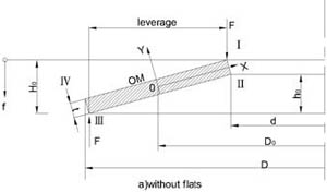
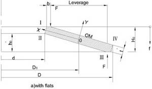

Technical and Design Guideline:
Material
| common used | |||||||
| material | Ck75 | 50 Cr V4 | X12CrNI 177 | X7CrNIAl 177 | X35CrMo17 | X22CrMoV 121 | |
| DIN | 1.1248 | 1.8159 | 1.4310 | 1.4568 | 1.4122 | 1.4923 | |
| Chemical components(%) | C | 0.7-0.8 | 0.47-0.55 | 0.12≤ | 0.09≤ | 0.35 | 0.2 |
| Si | 0.15-0.35 | 0.15-0.40 | 1.5≤ | 1≤ | 1≤ | 0.3 | |
| Mn | 0.6-0.8 | 0.7-1.1 | 2≤ | 1≤ | 1≤ | 0.6 | |
| P max | 0.035 | 0.035 | -- | -- | 0.03 | 0.035 | |
| S max | 0.035 | 0.035 | -- | -- | 0.03 | 0.035 | |
| Al | - | - | - | 0.75-1.5 | - | - | |
| Cr | - | 0.9-1.2 | 16-18 | 16-18 | 16.5 | 12 | |
| Ni | - | -- | 6-9 | 6.5-7.75 | - | 0.6 | |
| V | - | 0.1-0.2 | - | - | - | 0.6 | |
| Mo | - | - | - | - | 1.15 | 1 | |
| (N/mm2) | 206000 | 206000 | 190000 | 195000 | 206000 | 206000 | |
| Special material | |||||||
| material | Inconel X750 | Inconel 718 | Nimonic 90 | A286 Alloy | FV520B | CuBe2 | |
| DIN | -- | 2.4668 | 2.4969 | 1.4980 | -- | 2.1247 | |
| Chemical components(%) | C | 0.08≤ | 0.08£ | 0.09 | 0.08≤ | 0.048 | - |
| Si | 0.5≤ | 0.35 | 1≤ | 1 | 0.37 | - | |
| Mn | 1≤ | 0.35 | 1≤ | 2 | 1.05 | - | |
| P max | -- | 0.015 | -- | -- | 0.020 | - | |
| S max | 0.01 | 0.015 | 0.015 | -- | 0.014 | - | |
| Al | 0.4-1 | 0.2-0.8 | 1-2 | 0.35 | – - | - | |
| Cr | 14-17 | 17-21 | 18-21 | 13.5-16 | 16-18 | - | |
| Ni | ≤ 70 ≤ | 50-55 | Rest | 24-27 | 5.47 | +Co=0.2-0.6 | |
| V | - | - | - | 0.1-0.5 | - | - | |
| Mo | -- | 2.8-3.3 | -- | 1-1.75 | 1.72 | - | |
| W | -- | -- | -- | -- | -- | - | |
| Ti | 2.25-2.75 | 0.65-1.15 | 2-3 | 1.9-2.3 | 0.10 | - | |
| Be | - | - | - | - | - | 1.95 | |
| Cu | 0.5 | 0.3 | 0.2 | -- | 2.08 | Rest | |
| Co | -- | 1 | 15-21 | -- | -- | -- | |
| Fe | 5-9 | -- | 2 | -- | -- | -- | |
| Nb | 0.95 | -- | -- | -- | -- | -- | |
| (N/mm2) | 214000 | 208000 | -- | -- | -- | -- | |
Dimensional Tolerance
DIAMETER TOLERA
Outside Diameter: De
Inside Diameter: Di
| De or Di |
Permissible deviation De Di Concentricity | |||
| MM | MM | MM | MM | |
| 1 | Over 3 to 6 | 0/-0.12 | +0.12/0 | 0.15 |
| 2 | Over 6 to 10 | 0/-0.15 | +0.15/0 | 0.18 |
| 3 | Over 10 to 18 | 0/-0.18 | +0.18/0 | 0.22 |
| 4 | Over 18 to 30 | 0/-0.21 | +0.21/0 | 0.26 |
| 5 | Over 30 to 50 | 0/-0.25 | +0.25 | 0.32 |
| 6 | Over 50 to 80 | 0/-0.30 | +0.30/0 | 0.60 |
| 7 | Over 80 to 120 | 0/-0.35 | +0.35/0 | 0.70 |
| 8 | Over 120 to 180 | 0/-0.40 | +0.40/0 | 0.80 |
| 9 | Over 180 to 250 | 0/-0.46 | +0.46/0 | 0.92 |
| 10 | Over 250 to 315 | 0/-0.52 | +0.52/0 | 1.04 |
| 11 | Over 315 to 400 | 0/-0.57 | +0.57/0 | 1.14 |
| 12 | Over 400 to 500 | 0/-0.63 | +0.63/0 | 1.26 |
1) In reference to Outside Diameter De
THICKNESS TOLERANCE (t)
|
t or t’ MM |
Tolerance for t MM |
Group 1 |
0.2 to 0.6 |
+0.02 / -0.06 |
Group 2 |
1.25 to 3.8 |
+0.04 / -0.12 |
Group 3 |
>6.0 to 14.0 |
+0.10 / -0.10 |
FREE OVER-ALL HEIGHT (lo) TOLERANCE
|
t [MM] |
Tolerance for L0 |
Group 1 |
<1.25 |
+0.10 / -0.05 |
Group 2 |
1.25 to 2.0 |
+0.15 / -0.08 |
Group 3 |
>6.0 to 14.0 |
+0.30 / -0.30 |
SPRING FORCE TOLERANCE
The static load (F) of a single disc shall be determined for a disc in the loaded state using a suitable lubricant. The pressure plates between which the disc is compressed must be hardened ground and polished.
The following deviations apply for normal applications:
|
t[MM] |
Tolerances for F at the test length |
Group 1 |
<1.25 |
+25% / -7.5% |
Group 2 |
1.25 to 3.0 |
+15% / -7.5% |
Group 3 |
>6.0 to 14.0 |
+5% / -5% |
Surface Finish
Zinc phosphatizing and oiling ,oxidized bluing are the standard corrosion protection methods used for disc spring transport and storage. Special coatings, such as zinc plating, Delta Tone/Delta Seal, Geomet or chemical nickel plating are also available.
Application
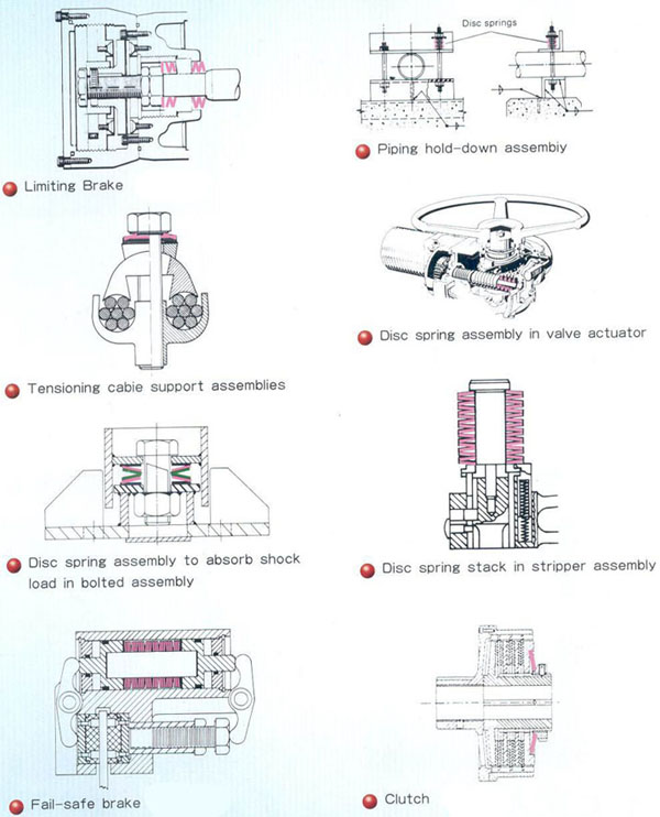
Typical Application
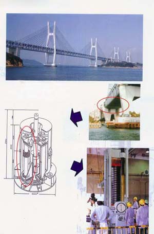
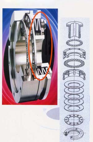
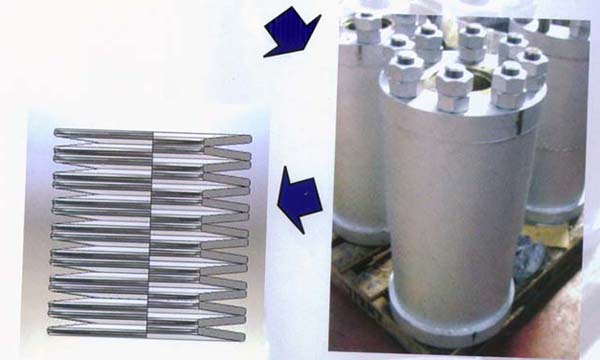
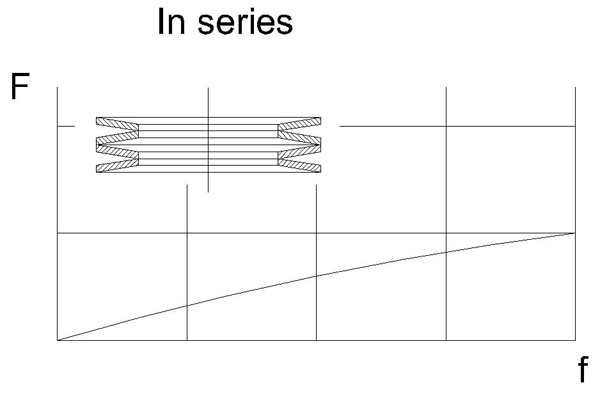
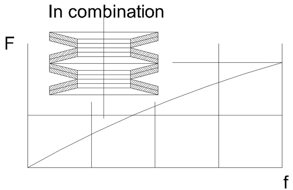
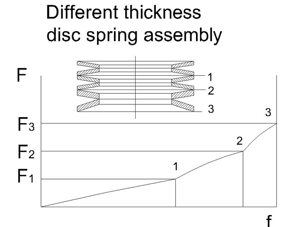
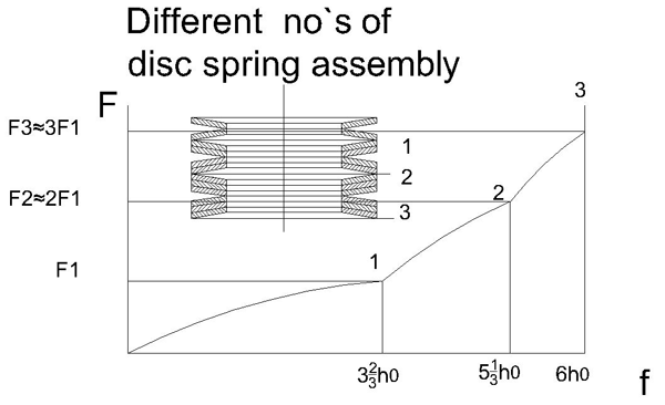
Stacking
Production Process
Fine blanking
Disc springs with material thickness between 1mm and 6mm are generally fine blanked.this method improves the fatigue life of the spring
Shot peening process
All Shuangyuan disc springs are shot peened using standard methods. The residual compressive stresses introduced to the peripheral layer through shot peening significantly increase the service life of the springs.
Heat Treatment
The heat treatment of disc springs is a fundamental
Production step for achieving the required spring character-
Istic.Depending upon the spring dimensions,modern
Continuous feed furnaces or chamber ovens are avaiable.
We have austempering and quenching and tempering
Processes available.
Pre-setting
Set loss can occur due to high stresses of the spring.in oder to reduce the risk of set loss,Shuangyuan pre-sets all disc springs at least to the flat position.this process greatly improves the quality of the spring and therefore is a requirement of the DIN 2093 standard
Phosphating
The standard corrosion protection,zinc phosphating and oiling,is made with afully automated continuous flow process,which guarantees uniform coating thickness at a reasonable cost
Delivery of disc spring stacks
Disc springs are often used in pre-assembled stacks.Shuangyuan is able to deliver pre-assembled stacks and if desired,
Install these stacks in the final assembly device.Shuangyuan can also manufacture these assembly devices per customer request.Test certificates(e.g.100% load testing) can also be provided upon request.
Applications with disc springs in use
o Control Safety Valve
o Automatic Quick Tool Changer (CNC Machines, etc.)
o Torque Converter
o Clutches Manual Transmission
o Nozzle of Spray Injection Moulding Unit
o Brake System
o Brake Slack Adjuster
o Stamping Machine
o Damper
o Over Load Protection